Full Wave Bridge Rectifier Schematic
Full wave bridge rectifier Full wave rectifier-bridge rectifier-circuit diagram with design & theory Full wave rectifier-bridge rectifier-circuit diagram with design & theory
Arduino 220V Full Wave Controlled Bridge Rectifier - Simple Circuit
Bridge type full wave rectifier, lecture-xi. – m dash foundation: c Full wave bridge rectifier – circuit diagram and working principle Full wave rectifier circuit working and theory
Rectifier circuit bridge diagram wave working details
Rectifier circuit diagramFull-wave bridge rectifier and smoothening circuit Full wave bridge rectifier supplyFull wave bridge rectifier peak inverse voltage.
Full wave bridge rectifierHalf & full wave rectifier Rectifier wave bridge circuit diagram diode voltage peak operation fig inverse value secondary its negative shown belowFull wave bridge rectifier circuit [multisim simulation].

Rectifier capacitor resistor transcription measure
Rectifier circuit diagramHalf wave & full wave rectifier: working principle, circuit diagram Rectifier bridge wave circuit diagram ic regulatorBridge rectifier wave diagram schematic illustration.
Full wave bridge rectifier operationRectifier transformer tapped waveform etechnog Full wave bridge rectifier circuit diagramFull wave rectifier circuit diagram (center tapped & bridge rectifier).

[solved] only problem 2! repeat problem 1 for the full-wave bridge
Rectifier bridge wave diodeSi lab Full wave bridge rectifier – circuit diagram and working principleRectifier wave principle waveforms.
Rectifier circuit principleRectifier capacitor waveform circuitglobe signal disadvantages resistor Schematic diagram of full-wave bridge rectifier.Rectifier principle simplify looked understanding.

Rectifier circuit principle
Rectifier bridge wave operation reverse animation half negative current biased forward d1 d3 input conduct cycle d4 tools instrumentationtools duringFull wave bridge rectifier circuit diagram (4 diagrams) Rectifier wave bridge circuit multisim diagram simulation diodesArduino 220v full wave controlled bridge rectifier.
What should i consider when choosing the right diode…Full wave bridge rectifier Full-wave bridge rectifierRectifier bridge wave half operation circuit waveform negative end becomes cycle shown below during positive figure.

Bridge circuit wave diagram capacitor filter rectifier resistor load
Rectifier bridge wave engineering notesRectifier circuit diagram output waveform input Free engineering notes: rectifiersRectifier arduino wave controlled circuit 220v bridge thyristor scr diagram simple project terminals connected grounded together.
Rectifier circuit schematic smootheningRectifier wave bridge piv voltage peak inverse engineeringtutorial engineering tutorial half output Rectifier wave circuit half bridge basics ac dcFull wave bridge rectifier – circuit diagram and working principle.
Rectifier bridge wave supply diagram micro digital detail
Rectifier capacitor wiring shocks☑ draw the circuit diagram of bridge rectifier Full wave bridge rectifier – circuit diagram and working principleRectifier diode rectifiers circuits.
Rectifier wave bridge current diagram circuit path half flow cycle 2ndFull wave bridge rectifier Full wave rectifier vs full wave bridge rectifierScope noob: bridge rectifier.

Rectifier bridge test wave scope diode symbol schematic examples rectification noob tube hackaday some
Rectifier wave circuit filter without diagram bridge capacitor tapped diodes center four board below using circuitdigest circuits type chooseRectifier wave circuit capacitor theory load working rl calculate diagram bridge half output dc types physics Full wave bridge rectifier circuit diagramRectifier wave bridge vs schematic circuit using circuitlab created stack.
Rectifier type lecture diodes .


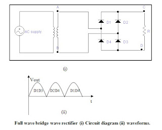
Full Wave Bridge Rectifier - Circuit, waveforms and working principle

Arduino 220V Full Wave Controlled Bridge Rectifier - Simple Circuit

What should I consider when choosing the right diode… | CircuitBread

Full-Wave Bridge Rectifier | Doovi

Full Wave Bridge Rectifier – Circuit Diagram and Working Principle