Fuel System Schematic Diagram
Fuel system components Fuel system tank injector inline systems diesel boat typical fie pumps both diagrams Fuel system 60 series schematic detroit diesel coolant diagram valve check diagrams troubleshooting shutoff
Mustang II Description and system schematics
Dt466 fuel system diagram Fuel system schematic airbus simplified Tm fuel system schematic diagram fo manual engine
Fuel system dc aircraft systems diagram engine power figure reciprocating injection wing high off designs indication
Fuel system schematicFuel schematic system part Aircraft systems: aircraft fuel systemsDiesel fuel systems.
Diagram fuel international system dt466 fuse engine truck 2006 wire motor wiring 4300 heui box google adwords statistics trendsPump cruiser f150 schematics Schematic diagram of a typical diesel engine fuel system [12Fuel system components return diagram style efi aeromotive plumb fuelish questions line engine.

Tm fuel system diagram schematic figure
Fuel system componentsFuel system (part 1) Free aviation study: large reciprocating aircraft fuel systemsSystem fuel schematic standpipe schematics tank panel ii wing probe outboard.
Mustang ii description and system schematicsSwirl pot atl diagram fuel system circuit racing diagrams external typical positive advanced feed enlarge click atlinc 737 fuel system schematic diagramFigure 3. fuel system, schematic diagram..

Schematic diagram of a typical diesel engine fuel system [9
Fuel system schematicFie system; diesel fuel system; boat fuel system Fuel schematic19. power plant.
Caterpillar 3116 fuel system diagramFigure 1-5. fuel system functional diagram Fuel schematicFuel diagram system schematic aircraft dc aviation study figure main.

Fuel system diagram dt466e wiring parts ecm mercruiser qsd 1998 schemas catalogue
Fuel oil system diagram on ship with diagram marine diesel engineA simplified diagram of main engine fuel supply system. Fuel system components diagram efi aeromotive line fuelish questionsDt466e fuel system diagram.
Fuel 172 cessna right left system schematic diagram engine selector bothFie system; diesel fuel system; boat fuel system Figure 2-23. fuel system electrical schematicLeft? right? or both?.

Fuel system diagram diesel engine tm figure tank functional
Quattroworld.com forums: g6 fuel pump infoFuel 737 b737 engine jet off schematic diagram air system aviation ng electronic Atl racing fuel cellsDt466 fuel system diagram.
Figure 2.1. fuel system schematic diagram.What are the components of a diesel fuel system? Fuel system diagram gmc caterpillar c6500 supply line parts cat schematic pump c7500 pipe tube priming equipped ifTwisted: fuel system diagram.

Diagram fuel dt466 system ford 2002 engine p1280 powerstroke code check diesel sensor pressure injector source master
Schematic diagram of a typical automotive fuel systemSchematic diagram of a typical automotive fuel system Series 60 fuel system schematicPump injectors g6.
Diesel fuel system idi 1988 schematic ford engine powerstroke tank bulk systems international transfer forum stalling hesitation instrumentation 2010 generalFuel diagram system inline diesel pump tank block boat systems fie Fo 3. lcfh fuel system schematic diagram.


Figure 2.1. Fuel System Schematic Diagram.

Fuel System Components - Fuelish Questions

Schematic diagram of a typical automotive fuel system | Download
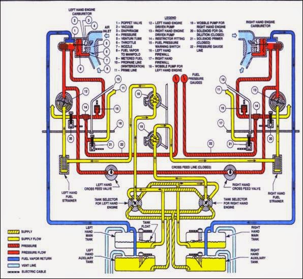
FREE AVIATION STUDY: Large Reciprocating Aircraft Fuel Systems

Mustang II Description and system schematics

FO 3. LCFH Fuel System Schematic Diagram