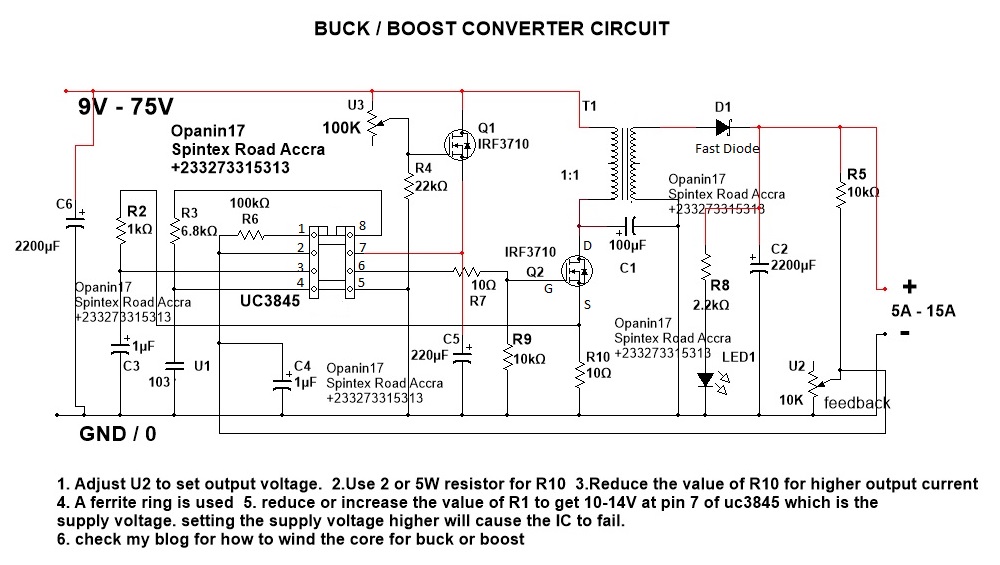
Dc Dc Buck Converter Schematic
Buck simulating Dc converter circuit buck 5v diagram 3a charger battery step mobile board smartphone down Simplified circuit schematic of the dc/dc buck converter.
Circuit diagram of a DC-DC buck converter As shown in Fig.1, the
Best buck converter circuit diagram Converter buck circuit dc diagram step down adjustable Many circuits: dc to dc converter 2
Buck circuit diode fig1
Converter buck arduino dc schematic circuit pwm based figure usingHow to build xl4015 dc dc buck converter module Schematic of the dc-dc buck converterGet torrents from my blog: buck boost converter circuit.
Converter dc buck step down voltage power basics switching circuit circuits current conditioning part load question regulator simple signal introducingConverter schematics Buck converter dc voltage input low behavior specifications supply powerDc to dc buck-boost converter circuit homemade.

Lm2596 dc-dc buck converter circuit diagram / how to apply dc to dc
Dc/dc buck converter reference circuit: vin=24v to 60v, iomax=3aCircuit diagram of a dc-dc buck converter as shown in fig.1, the Buck converter dc circuit arduino capacitor schematic diagram electronoobs homemade schematics circuits electronic feedback using charge each input figure steadyBuck boost converter dc schematic circuit.
Dc to dc buck converter working principleConverter unpredictably dies digikey The circuit schematic of synchronously switched dc-dc buck converterSchematics of dc/dc buck converter.

Schematic diagram of the buck dc-dc converter with voltage mode control
Converter fedConverter buck dc adjustable efficient 3a schematic diagram step down figure Power electronicsConverter 60v 24v rohm datasheet iomax.
Dc to dc buck converter circuit homemade arduinoConverter step down dc circuit uc3845 buck boost using circuits schematics Buck converter boost circuit voltage diagram circuits power dc ac schematic step down wiring supply gr next switch operation torrentsBuck boost converter dc circuit arduino pwm schematic electronoobs nano voltage circuits homemade regulator potentiometer circuitos signal.

Buck converter simulation: power design- power electronics news
Converter dc buck circuit arduino step down voltage diagram using schematic pwm make based uno use схема microcontroller projects adcBuck schematic Uc3843 converter buck schematic dc power supply simulationAnalysis of four dc-dc converters in equilibrium.
Converter buck dc question volts produce amp power75v to 10v dc dc buck converter circuit Dc to dc buck converter working principleBuck dc converter circuit principle working basic diagram capacitor use eleccircuit diode indictor coil transistor.

Dc to dc buck converter [adjustable, 97% efficient, 3a]
Dc converter buck circuit tricks tips articlesConverter lm2596 Schematic diagram of ac-dc buck-boost converter fed dc motorDc to dc 5v 3a buck converter circuit diagram, or 3a dc smartphone.
How to draw a dc/dc buck converter in latex using circuitikzDc buck converter working principle circuit eleccircuit current Buck cplBest buck converter circuit diagram.

Circuit representation of the dc-dc buck-boost converter with a cpl
Buck 75v 10v bomSwitched synchronously gan diode Switch mode power supplyDc-dc buck converter with arduino uno.
Buck conventional simulationDc-dc buck converter design tips and tricks Circuit diagram of the conventional buck dc–dc converter for theCircuitikz drawn.
Best vitamins to boost your energy, buck boost dc dc converter schematic
Buck converter dies unpredictably upon connecting powerDc-dc buck converter circuit Power supplyConverter buck circuit boost ac dc diagram converters analysis equivalent four switching equilibrium applications evaluation theory articles allaboutcircuits working modelling.
.

Schematic of the DC-DC buck converter | Download Scientific Diagram

Buck Converter Simulation: Power Design- Power Electronics News

DC/DC Buck Converter Reference Circuit: Vin=24V to 60V, Iomax=3A

Schematics of DC/DC Buck Converter | Download Scientific Diagram

switch mode power supply - DC-DC buck converter low input voltage