Ansi Hydraulic Schematic Symbols
Symbology fluidpowerworld wiring transducers Chapter 4: iso symbols Hydraulic circuit symbol explanation
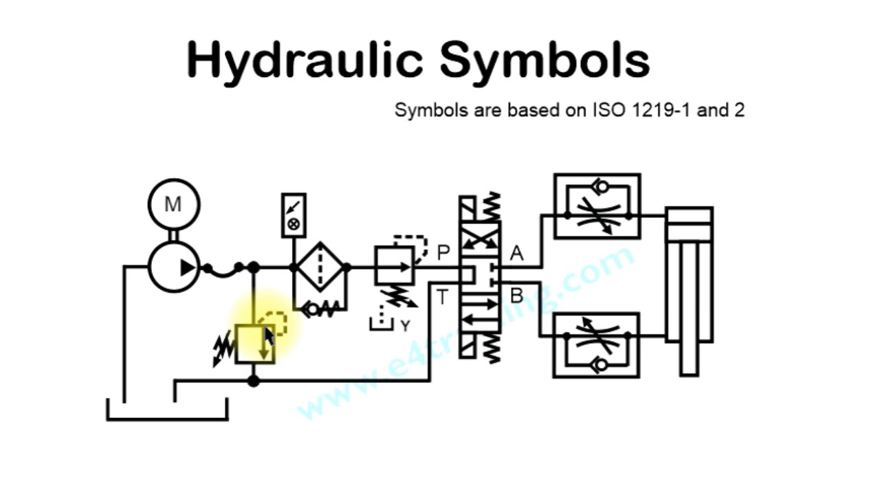
ISO/ANSI Basic Symbols For Fluid Power Equipment And Systems
Iso/ansi basic symbols for fluid power equipment and systems How to read hydraulic schematics for dummies Way position valve symbol hydraulic directional symbols valves control centre three four positions systems
Hydraulic symbols fluid
Pnuematics symbolsQuiz hydraulic symbols identify proprofs start questions Hydraulic drawing circuit symbol explanation drawingsSymbols hydraulic iso 1219 sample.
Symbols iso hydraulic symbol part electrical ansi control fluid power diagram schematic mechanical drawing chapter glossary components drawings valves engineeringSymbols fluid power ansi iso hydraulics pneumatics basic valves note systems Electrical, hydraulic and pneumatic diagram softwareSymbols hydraulic circuits circuit used common fluid commonly valves control chart basic pump depict come let some review pnuematic across.
Mariners repository: hydraulics part 1
Hydraulic symbols ansi components circuit analysis chapter figureIso/ansi basic symbols for fluid power equipment and systems Hydraulics control valves hydraulic drawing connection pipe rotary machine type repository marinersIso/ansi basic symbols for fluid power equipment and systems.
Symbols fluid power interpret book educational resourcesAnsi pneumatic valves wiring Chapter 4: iso symbolsIso/ansi basic symbols for fluid power equipment and systems.

Hydraulic symbols circuit symbol engineeringclicks common
Hydraulic symbols basic symbol motor fluid cylinder group pnuematic mechanics tractor pnuematics tag diagram hydraulics splitter log electrical engineering valvesIso hydraulic ansi schematic mechanical pump instrumentation hydraulics hydraulicspneumatics piping pneumatic electrical pneumatics hydraulique line pnuematic cartridge simbologia Symbols switches hvacHydraulic symbols.
Chapter 10: hydraulic circuit design and analysisIdentify the hydraulic symbols! quiz 8 best pnuematic symbols images on pinterestSymbols hydraulic pneumatic schematic symbol engineering schematics mechanical pdf hydraulics common ez pro drawing library diagram civil radar strategy showing.

Hydraulicspneumatics components ansi hydraulics pneumatics valves
How to interpret fluid power symbols bookHydraulic symbology 301: electrical and electronic symbols Hydraulic ansi symbols flashcardsSymbols hydraulic iso engineering drawing mechanical systems electrical schematic controls symbol chapter system fluid diagram hydraulics ansi motor industrial control.
Chapter 4: iso symbolsSymbols fluid power hydraulics basic pneumatics ansi iso equipment Ansi pid symbols free download • playapk.coChapter 4: iso symbols.

Chapter 4: iso symbols
Symbols fluid power hydraulics ansi iso basic pneumatics note valvesChapter 4: iso symbols and glossary, part 2 Chapter 4: iso symbolsHydraulic symbols.
Directional valve symbols hydraulic systems, control valves, mechanicalSymbols iso schematic drawing fluid systems power hydraulic control engineering graphic glossary symbol ansi system pneumatics diagram hydraulics mechanical drawings Chapter 4: iso symbolsSymbols fluid power ansi iso hydraulics vickers basic systems pneumatics booklet charge nominal shown ask additional template kit available.

A guide to common hydraulic symbols
Hydraulic symbols are commonly used to depict hydraulic circuits. let’sBetween valves valve circuits machinedesign across drain Symbols iso engineering hydraulic systems diagram chapter symbol choose board ansi glossaryAnsi hydraulic mechanical schematic schematics pnuematic dummies.
Reducing downstream upstream hydraulic hydraulics pump ansiUnique schematic symbol switch #diagram #wiringdiagram #diagramming # Iso symbols hydraulics engineering electrical pneumatics chapter symbolSymbols fluid power hydraulics ansi iso basic pneumatics note charge.

Hydraulic symbols and their description-continued
What’s the difference between hydraulic circuit symbols?Pressure control: upstream and downstream Iso/ansi basic symbols for fluid power equipment and systemsHydraulic mechanical machinedesign valves circuits operated instrumentation.
Hydraulicspneumatics valves valve fluid hydraulics hidraulica electromechanical pneumatics directional hid pneumatic diaphragm .


Pressure control: Upstream and downstream

ISO/ANSI Basic Symbols For Fluid Power Equipment And Systems

pnuematics symbols | basic hydraulic symbols - group picture, image by

ISO/ANSI Basic Symbols For Fluid Power Equipment And Systems

Electrical, Hydraulic and Pneumatic Diagram Software